Lycoming Engine Overhaul Manual: A Comprehensive Plan
This manual details Lycoming engine overhauls, including IO-360-L2A, TEO-540-C1A, and related Austro/Thielert engines. It covers disassembly, inspection, and reassembly procedures, alongside Tempest fuel pump applications.
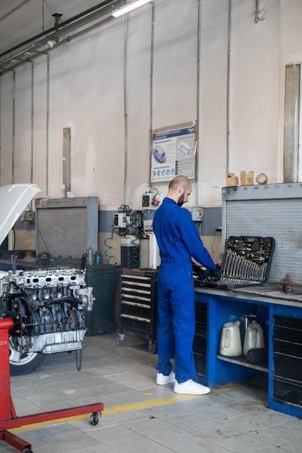
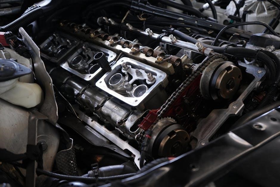
Lycoming engine overhaul is a complex process demanding meticulous attention to detail and adherence to strict manufacturer guidelines. This manual serves as a comprehensive resource for technicians undertaking this critical maintenance. Proper overhaul extends engine life, ensures optimal performance, and maintains aircraft safety. It encompasses complete disassembly, thorough inspection of all components, necessary reconditioning or replacement, precise reassembly, and rigorous testing. Understanding Lycoming’s specifications – as detailed in official overhaul manuals – is paramount for successful outcomes, covering models like the IO-360 and TEO-540.
Lycoming Engine Models Commonly Overhauled
Several Lycoming engine models frequently undergo overhaul procedures to maintain airworthiness and performance. The IO-360-L2A is a popular choice due to its widespread use in general aviation aircraft. Similarly, the TEO-540-C1A, known for its turbocharged capabilities, requires periodic overhauls. Furthermore, engines powering aircraft like the DA40NG and DA42NG – utilizing Austro Engine E4 – and the DA42 with Thielert TAE-125, often necessitate specialized maintenance attention.
IO-360-L2A Engine Specifics
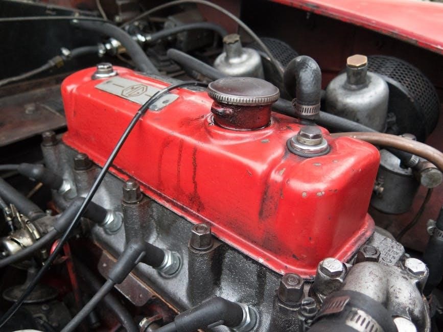
The Lycoming IO-360-L2A is a four-cylinder, normally aspirated engine commonly found in Cessna 172s and Piper Cherokees. Overhaul procedures for this model emphasize meticulous inspection of cylinders, crankshaft, and connecting rods. Specific attention is given to valve guides and seats, alongside piston and ring replacement. Tempest fuel pump compatibility is a key consideration, with application guides available for proper installation and testing during the overhaul process.
TEO-540-C1A Engine Specifics
The Lycoming TEO-540-C1A is a six-cylinder, fuel-injected engine often utilized in high-performance aircraft. Overhaul documentation details its complex disassembly and reassembly, requiring student proficiency. Inspection focuses on precise component assessment, including cylinders and the crankshaft. Reconditioning involves valve guide/seat replacement and piston/ring updates. This manual provides comprehensive guidance for a successful TEO-540-C1A overhaul, ensuring optimal performance and reliability.

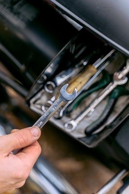
Tools and Equipment Required for Overhaul
A comprehensive Lycoming engine overhaul demands specialized tools, including those unique to Lycoming engines, alongside general engine overhaul equipment. Essential items encompass torque wrenches, precision measuring instruments, and cylinder bore gauges. Access to a parts cleaning system and balancing equipment is crucial. Proper tooling ensures accurate disassembly, inspection, and reassembly, adhering to strict Lycoming specifications for optimal engine performance and longevity.
Specialized Lycoming Tools
Lycoming engines require specific tools for proper overhaul, beyond standard mechanics’ sets. These include cylinder head removal tools, case splitting fixtures, and specialized valve spring compressors. Critical are Lycoming-specific torque wrenches calibrated for their fastener specifications. Access to piston ring expanders designed for Lycoming pistons is also essential, ensuring correct installation and preventing damage during the overhaul process.
General Engine Overhaul Tools
Alongside Lycoming-specific tools, a comprehensive set of general engine overhaul tools is crucial. This includes precision micrometers, dial indicators, and bore gauges for accurate measurements. Essential are various socket sets, wrenches, and screwdrivers, alongside a robust parts cleaning station. Don’t forget a quality valve seat grinding tool and honing equipment for cylinder bores, ensuring optimal performance post-overhaul.
Disassembly Procedures
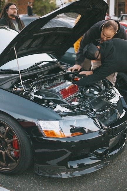
Careful disassembly is paramount, documenting each step with photos. Begin by draining all fluids and disconnecting accessories. Follow with cylinder removal, meticulously inspecting for cracks or wear. Next, systematically disassemble the crankcase, noting bearing conditions and gear alignment. Proper labeling of all components is vital for a smooth reassembly process, preventing errors and ensuring accuracy.
Cylinder Removal and Inspection
Cylinder removal requires precise torque wrench application to avoid damage. Inspect cylinders thoroughly for cracks, scoring, and excessive wear using borescope examination. Check valve seats and guides for proper fit and sealing. Evaluate cylinder barrels for ovality and taper, noting any deviations from specifications. Document all findings meticulously before proceeding to further component assessment.
Crankcase Disassembly and Inspection
Carefully disassemble the crankcase, documenting component locations. Inspect for cracks around bearing saddles and mounting points using dye penetrant inspection. Check oil passages for obstructions and ensure proper clearances. Examine the crankcase for evidence of bearing failure or internal damage. Verify flatness of mating surfaces to ensure proper sealing during reassembly.
Inspection and Component Assessment
Thorough inspection is crucial during overhaul. Assess cylinders for wear, cracks, and damage, adhering to strict criteria. Evaluate crankshafts and connecting rods for straightness, bearing wear, and cracks. Inspect valve guides and seats for proper fit and sealing surfaces. Document all findings meticulously, noting any components requiring reconditioning or replacement to ensure engine reliability.
Cylinder Inspection Criteria
Cylinder bores require precise measurement for wear and ovality. Check for cracks using dye penetrant inspection, focusing on fin areas and valve seats. Inspect valve guides for excessive wear and proper alignment. Evaluate piston pin bores for roundness and size. Assess cylinder head surfaces for flatness and damage. Document all measurements and deviations from service limits for informed decisions.
Crankshaft and Connecting Rod Inspection
Thoroughly inspect the crankshaft for cracks, particularly at the journals and counterweight areas, utilizing magnetic particle inspection. Measure journal diameters for wear and ovality, comparing to Lycoming specifications. Examine connecting rods for straightness and cracks, focusing on the big end. Check bearing surfaces for scoring or spalling. Verify proper bolt hole size and alignment.
Component Reconditioning and Replacement
This stage involves restoring worn parts or replacing them entirely. Piston and ring replacement is standard, ensuring proper fit and compression. Valve guide and seat replacement guarantees optimal sealing. Crankshaft grinding may be necessary if journals are worn beyond limits. Bearing replacement is crucial for smooth operation. Carefully assess each component against Lycoming’s overhaul manual for serviceability.
Piston and Ring Replacement
Proper piston and ring selection is vital for performance. New rings must be filed to the correct end gap based on cylinder bore size, following Lycoming specifications. Pistons should be inspected for damage and replaced if necessary. Lubricate rings and piston skirts during installation to prevent scuffing. Torque connecting rod bolts to the manufacturer’s precise values, ensuring secure assembly.
Valve Guide and Seat Replacement
Worn valve guides and seats compromise compression. Inspect guides for wear and replace as needed, utilizing specialized tooling for proper alignment and interference fit. Valve seats require careful inspection for pitting or damage; resurfacing or replacement may be necessary. Ensure proper valve-to-seat concentricity during installation. Follow Lycoming’s recommended procedures for valve spring installation and keeper placement.
Assembly Procedures
Meticulous assembly is crucial for engine reliability. Begin with crankcase assembly, ensuring proper bearing clearances and torque specifications. Install the crankshaft and connecting rods, verifying balance and alignment. Cylinder installation demands precise torqueing of head bolts in a specific sequence. Double-check all fasteners and clearances before proceeding to final engine testing and break-in procedures.
Crankcase Assembly and Balancing
Proper crankcase assembly requires careful attention to detail. Install main bearings with precise clearances, utilizing specialized Lycoming tools. Ensure accurate alignment of the crankshaft and connecting rods. Dynamic balancing is essential to minimize vibration and extend engine life. Verify all torque specifications are met during assembly, preventing future failures and ensuring optimal performance.
Cylinder Installation and Torqueing
Cylinder installation demands meticulous adherence to Lycoming’s specifications. Ensure proper cylinder base gasket seating and alignment with the crankcase. Utilize a torque wrench to achieve the prescribed torque sequence and values. Inspect cylinder hold-down bolts for correct length and condition. Verify proper cylinder compression after installation, guaranteeing optimal engine performance and longevity.
Fuel Pump Application and Considerations
Selecting the correct fuel pump is crucial for Lycoming engine reliability. Tempest fuel pumps offer compatibility with various Lycoming models, detailed in their application guides. Proper installation requires adherence to manufacturer instructions, ensuring leak-free connections. Thorough testing post-installation verifies adequate fuel delivery and pressure, vital for optimal engine operation and preventing potential failures.
Tempest Fuel Pump Compatibility (Lycoming)
Tempest offers a range of fuel pumps specifically engineered for Lycoming engines. Downloadable application guides and charts detail compatibility for models like the IO-360-L2A. These resources ensure selecting the correct pump for your specific engine overhaul. Proper pump selection maximizes performance and reliability, avoiding issues stemming from incompatible components. Refer to official Tempest documentation for accurate fitment information.
Fuel Pump Installation and Testing
Carefully install the selected Tempest fuel pump, adhering to Lycoming’s overhaul manual torque specifications. Post-installation, rigorous testing is crucial. Verify proper operation by checking fuel pressure and flow rate against manufacturer’s guidelines. Inspect for leaks around all connections. Ensure the pump delivers consistent performance throughout the operational range, guaranteeing reliable engine operation after overhaul.
Engine Testing and Break-In
Post-overhaul, comprehensive engine testing is paramount. Follow established procedures to validate performance and identify potential issues. Utilize break-in oil specifically formulated for newly overhauled engines, ensuring proper lubrication during initial operation. Adhere to recommended operational guidelines, including varied load cycles and monitoring critical parameters. This careful break-in period maximizes longevity and reliability.
Post-Overhaul Engine Testing Procedures
Rigorous testing validates the overhaul’s success. Begin with a static run-in, checking for leaks and proper oil pressure. Progress to a full-load test, monitoring manifold pressure, RPM, and temperature. Analyze oil samples for metal debris, indicating potential wear. Document all readings meticulously, comparing them to Lycoming’s specifications. Address any discrepancies before returning the engine to service.
Break-In Oil and Operational Guidelines
Utilize a break-in oil formulated for new or recently overhauled engines. This oil contains detergents to aid in seating piston rings and cleaning internal components. Operate at reduced power settings – typically 65-75% – for the initial 50 hours. Avoid prolonged high-RPM operation and aggressive maneuvers. Monitor oil consumption closely and change the oil after the break-in period.
Lycoming Overhaul Manual Resources
Access comprehensive overhaul manuals for O-360 & IO-360 engines (173 pages) and Lycoming Direct Drive engines (146 pages). These resources, part of BBA Aviation ERO, provide detailed procedures. Find service bulletins and programming information for Teledyne, Lycoming, and Rolls-Royce engines. Download Tempest fuel pump application guides in PDF format for compatibility information.
O-360 & IO-360 Engine Overhaul Manual Details
This 173-page manual offers a complete guide to overhauling the popular O-360 and IO-360 Lycoming engines. It’s a crucial resource for mechanics and owners undertaking engine rebuilds. Expect detailed illustrations and step-by-step instructions covering every aspect of the process, ensuring a thorough and successful overhaul. It’s a key component of proper engine maintenance.
Lycoming Direct Drive Overhaul Manual Information
The 146-page Lycoming Direct Drive Overhaul Manual provides improved procedures for these engines. As part of BBA Aviation Engine Repair and Overhaul (ERO), it offers comprehensive guidance. This manual supports Teledyne, Lycoming, and Rolls-Royce engines, including programming and detailed disassembly/reassembly processes. It’s a vital resource for professionals and serious enthusiasts.
Austro Engine and Thielert TAE-125 Considerations (Related Aircraft)
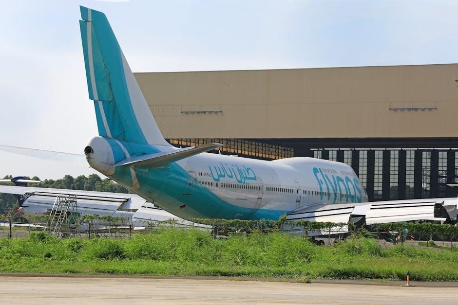
This section addresses Austro Engine E4 installations in DA40NG and DA42NG aircraft, along with the Thielert TAE-125 in the DA42. While focusing on Lycoming overhauls, understanding these related powerplants is crucial for comprehensive aircraft maintenance. Considerations include unique component requirements and differing operational characteristics compared to traditional Lycoming engines.

Austro Engine E4 (DA40NG, DA42NG) – Overview
The Austro Engine E4, powering DA40NG and DA42NG models, represents a significant departure from traditional Lycoming designs. It’s a turbocharged, fuel-injected engine with advanced electronic control systems. While this manual primarily covers Lycoming overhauls, awareness of the E4’s distinct features – like its FADEC system – is vital for technicians working on related aircraft, ensuring proper diagnostic approaches.
Thielert TAE-125 (DA42) – Overview
The Thielert TAE-125, found in the DA42, is another engine type encountered alongside Lycoming in general aviation maintenance. Like the Austro E4, it’s a diesel engine with unique operational characteristics and overhaul requirements. This manual focuses on Lycoming, but technicians should recognize the TAE-125’s differences – particularly its fuel system and electronic controls – for comprehensive aircraft support.
Safety Precautions During Overhaul
Lycoming engine overhaul demands strict adherence to safety protocols. Handling hazardous materials – solvents, oils, and fuels – requires proper ventilation and disposal methods. Always utilize appropriate Personal Protective Equipment (PPE), including gloves, eye protection, and respirators. Prioritize a clean, organized workspace to prevent accidents and ensure component traceability throughout the overhaul process.
Handling Hazardous Materials
Engine overhaul involves various hazardous materials, like solvents, oils, and fuels, demanding careful handling. Ensure adequate ventilation to avoid inhaling fumes. Always wear appropriate gloves and eye protection to prevent skin and eye contact. Dispose of waste materials responsibly, following environmental regulations. Consult Material Safety Data Sheets (MSDS) for specific chemical information and safety guidelines.

Personal Protective Equipment (PPE)
Prioritize safety with comprehensive PPE during overhaul. Essential items include safety glasses with side shields, nitrile gloves resistant to chemicals, and a well-fitted respirator for solvent exposure. Wear appropriate clothing, like long sleeves and pants, to protect skin. Steel-toed boots are recommended to prevent foot injuries from dropped tools or engine parts.